
|

|
|
|
ONEX #54 Web Site
|
Date: 2-18-2013
|
Number of Hours: 5.00
|
Manual Reference: C01, L02
|
Brief Description: Rudder controls
|
|
Temporarily installed the rudder, updrilled the control arm, and connected the rudder cable with the AN3 hardware.
The rudders have been moved aft 4", so a new pivot hole was located on the cable adjusters C03-24, updrilled and mounted to the rudder pedals. The forward end of the adjusters was too low to align with the specified bulkhead penetration, so the adjusters were cut 1-3/8" from the rudder pivot point, which would have been the position of the end of the adjusters in the standard position. A hole was drilled 1" forward of the pivot point, duplicating the position of the original spring connection point. A link was fabricated to attach at the spring attachment point, which allows the steering cable to correctly align with the steering cable. I will need the nose gear assembly mounted to do final trim adjustments to make sure the nose gear is pointed forward and with the rudder in neutral.
Updrilled the firewall to mount the steering pulleys. There was a drawing revision (L02 7/17/12) to increase the firewall penetration from 3/8" to 1/2". The clevis cable ends on the provided steering cables (L02-06) will not fit through a 1/2" hole, so a 9/16" hole was made. Prior to drilling the firewall, I assembled the pulley with an AN460-416L thin washer between the pulley wheel and the bracket. This insures there will be a slight clearance between the pulley and brackets on final installation.
|
|
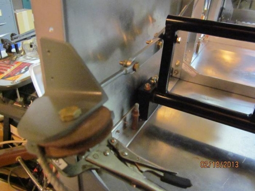
Articulated steering cable link
|
|
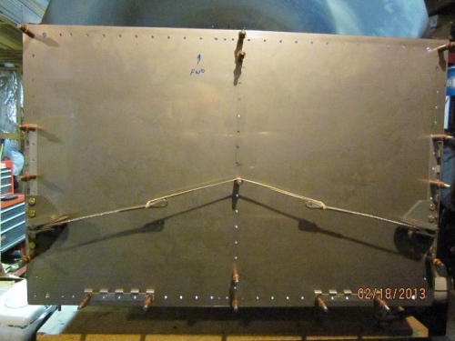
Steering pulleys fitted to firewall
|
|
|
|
|
|
|
|
|
Copyright © 2001-2024 Matronics. All Rights Reserved.
|